
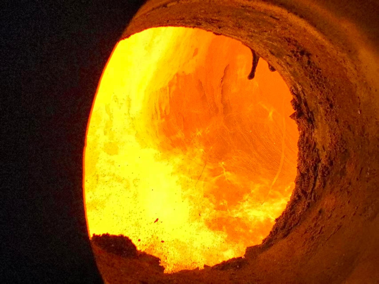
New product
High-melting ceramic-metal composite coating
Proven boiler protection against severe corrosion and slagging from high-temperature molten-salt fly ash. Our August 2026 case study combines successful field performance, operating inspections, laboratory validation, and thermal conductivity data to demonstrate reliable protection in demanding waste-to-energy applications.
90%
Reduction in deposit thickness on the rear arch
155 m²
Sprayed across #1 and #2 boilers
>15 months
Waterwall service life proven on hazardous waste
>0.45 mm
Applied coating thickness
1. Solving unplanned shutdowns at Xinyi Gaoneng caused by slag blockage
Background: The facility operates two 400 t/day waste-incineration boilers with sludge co-firing. In 2025, severe slag build-up on the front and rear arch side walls repeatedly restricted furnace operation, forcing two unplanned shutdowns and causing significant production disruption and financial losses. The plant required a reliable refractory solution to control slagging and restore stable, continuous operation.
#1 boiler — trial spray, 14 Jan 2026
Area: 40 m². Sprayed sections:
- Replaced castable at the bottom of the rear arch
- Partially replaced castable at the bottom of the front arch
- 1 m height of the side wall connecting the front and rear arches
- Waterwall around the ammonia-injection port
#2 boiler — spray, 5 Apr 2026
Area: 115 m². Sprayed sections:
- Front and rear arches and side walls below the auxiliary burner port (rear arch relined with new castable; other areas already flat)
- Waterwall around the ammonia-injection port
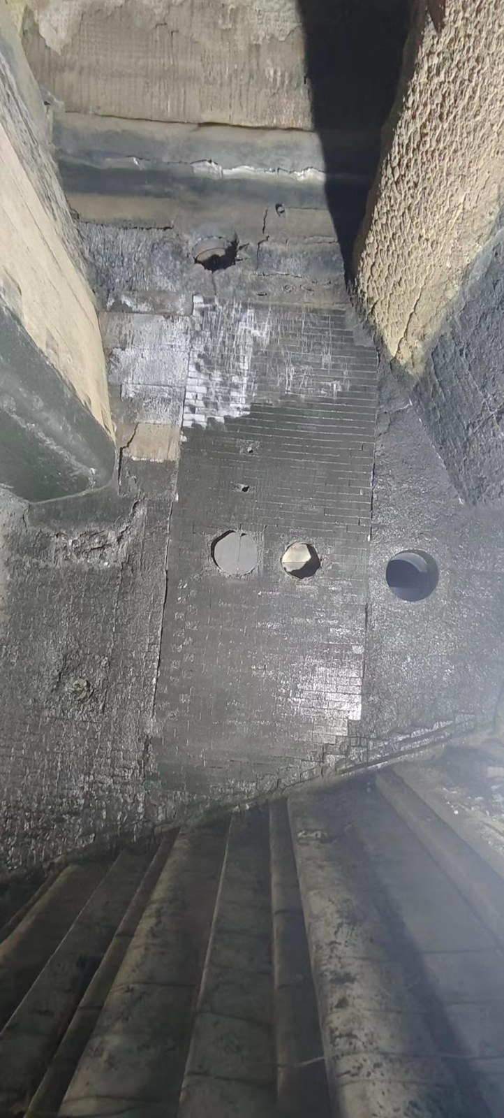
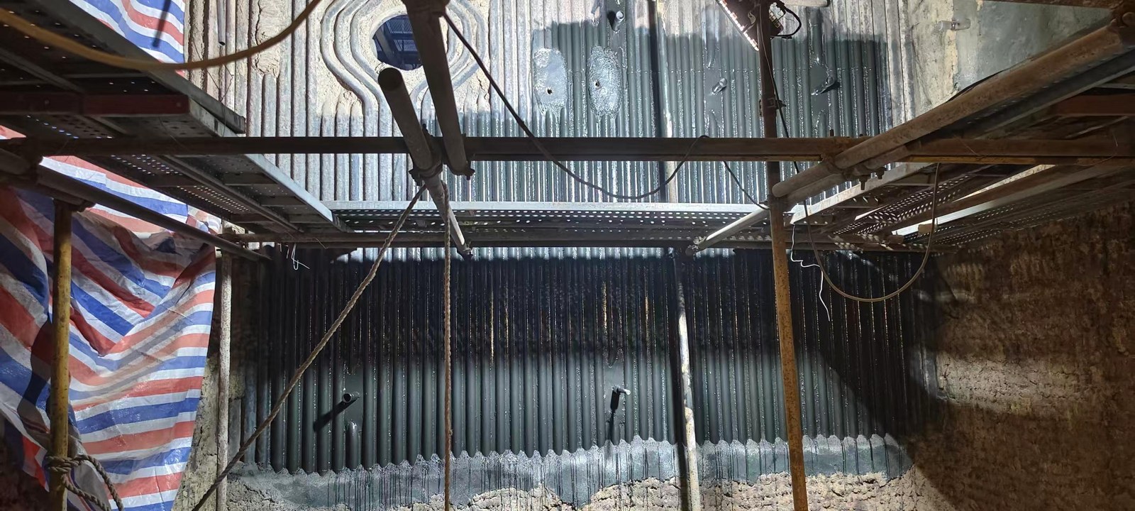
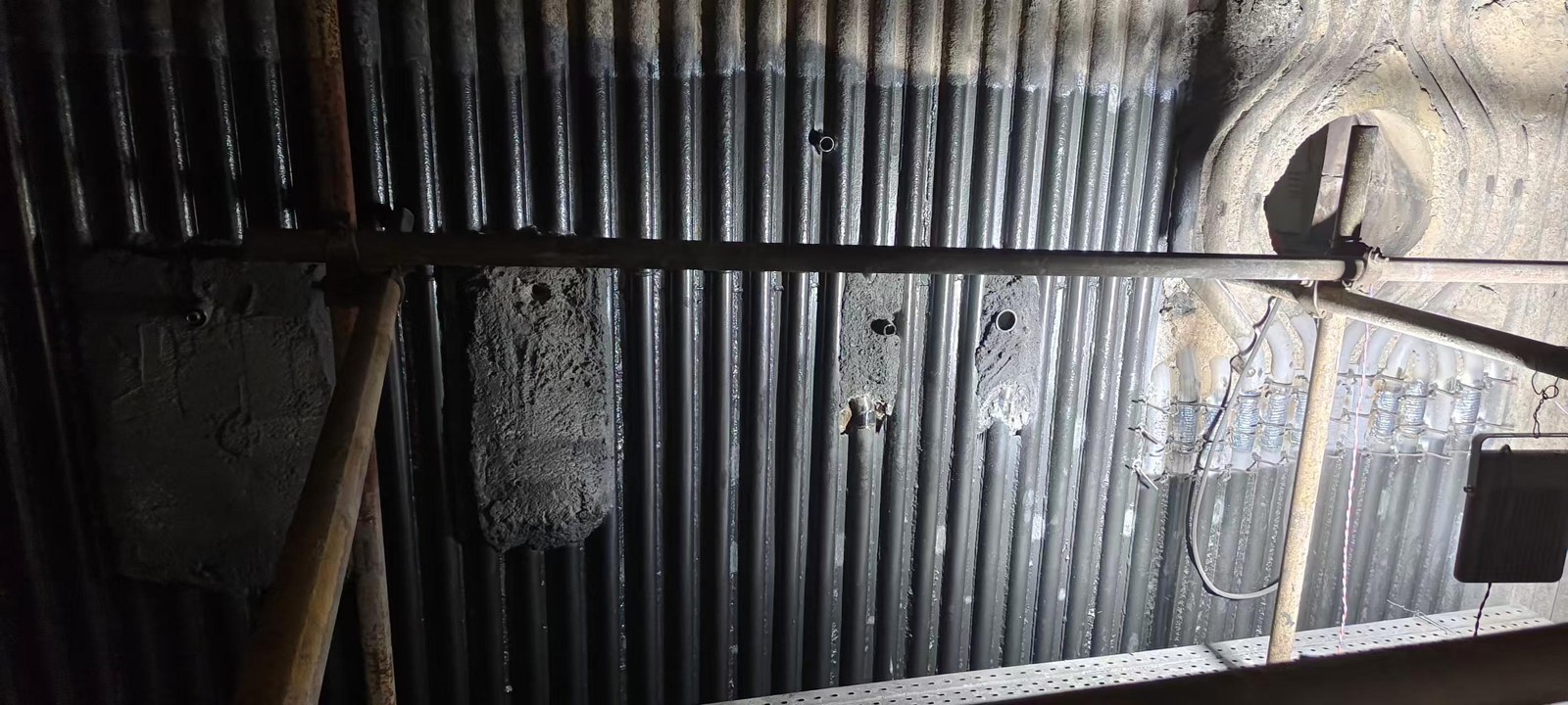
Shutdown inspection, 21 June 2026 (grid maintenance outage)
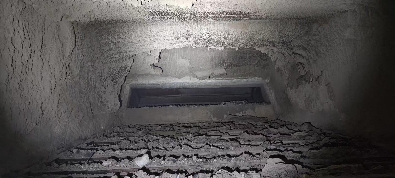
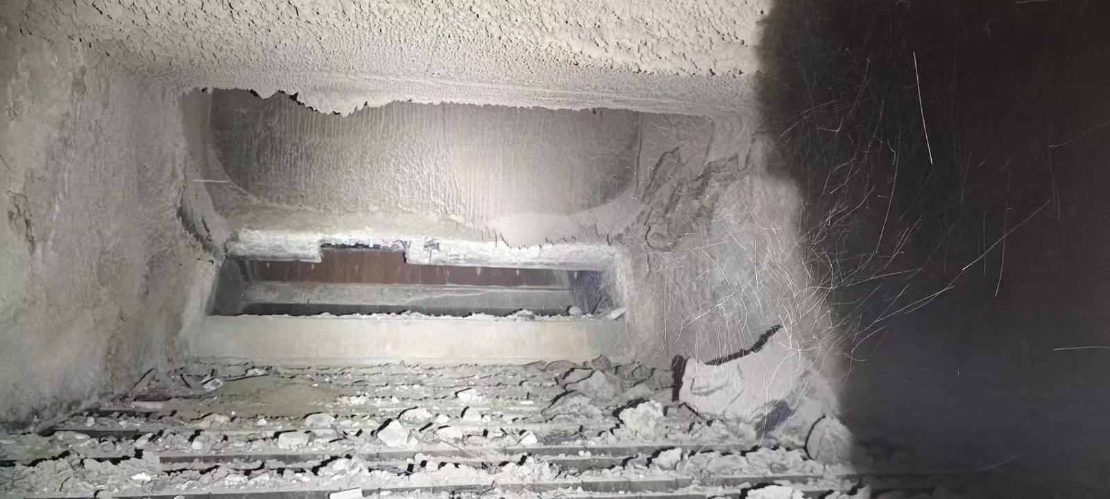
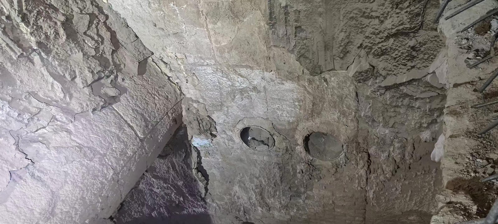
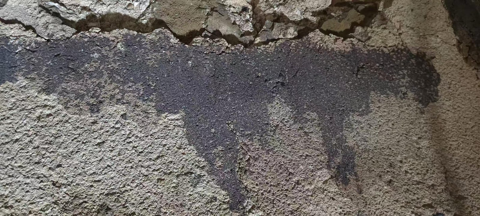
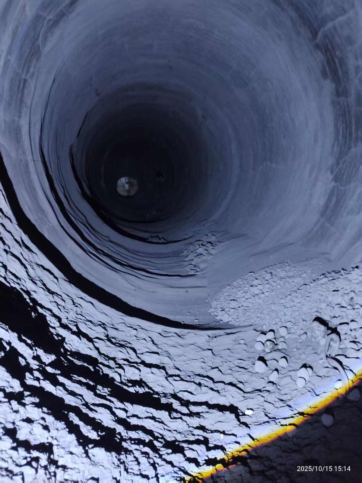
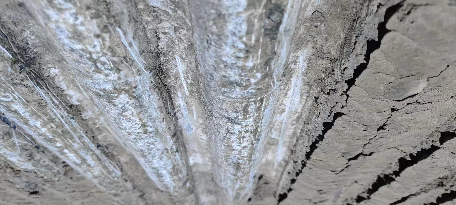
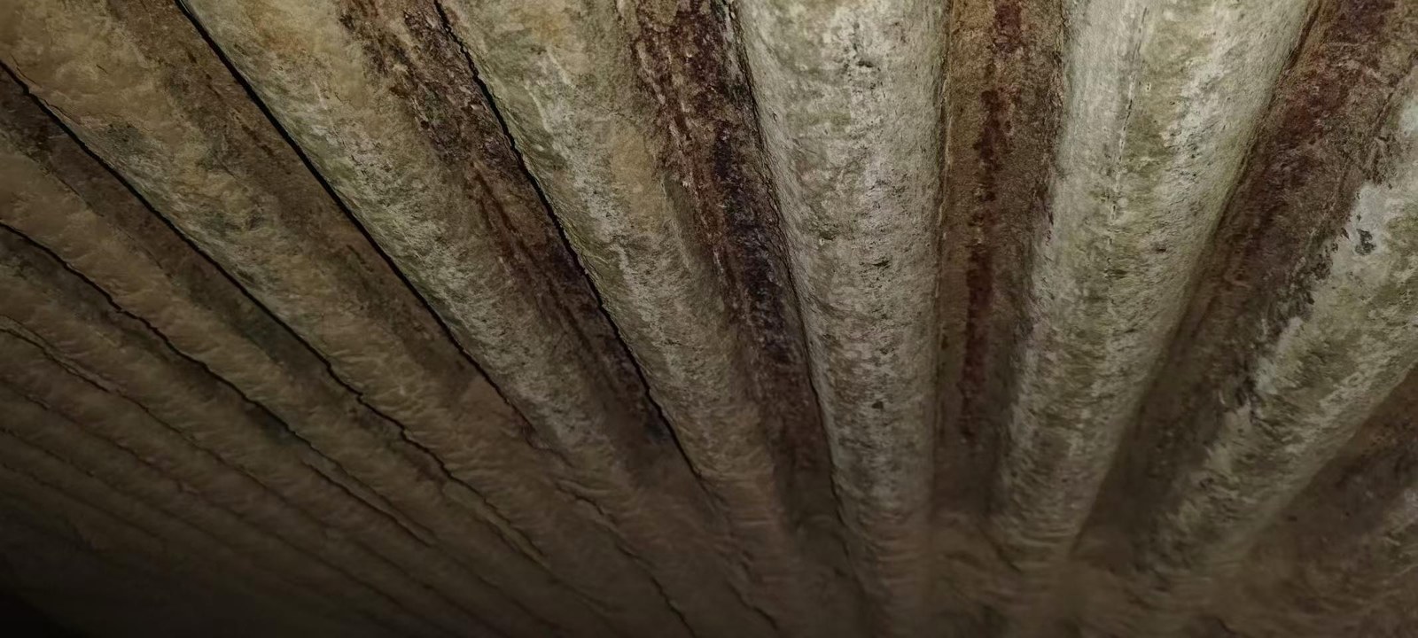
#1 boiler: rear arch covered by a 20–30 cm deposit layer in uncoated areas; after cleaning those areas were left uneven, while the coated areas stayed flat and the deposit fell away easily. The coating itself was undamaged.
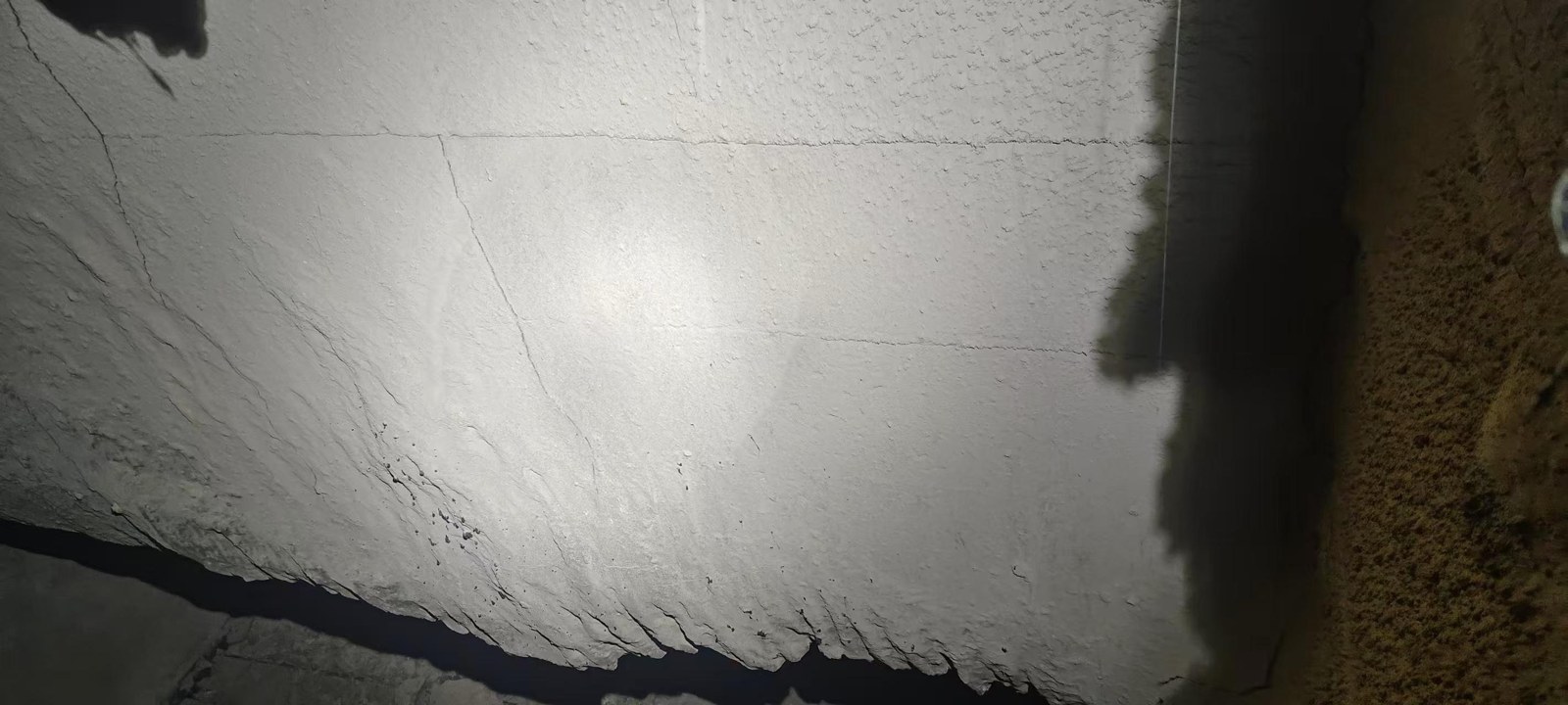
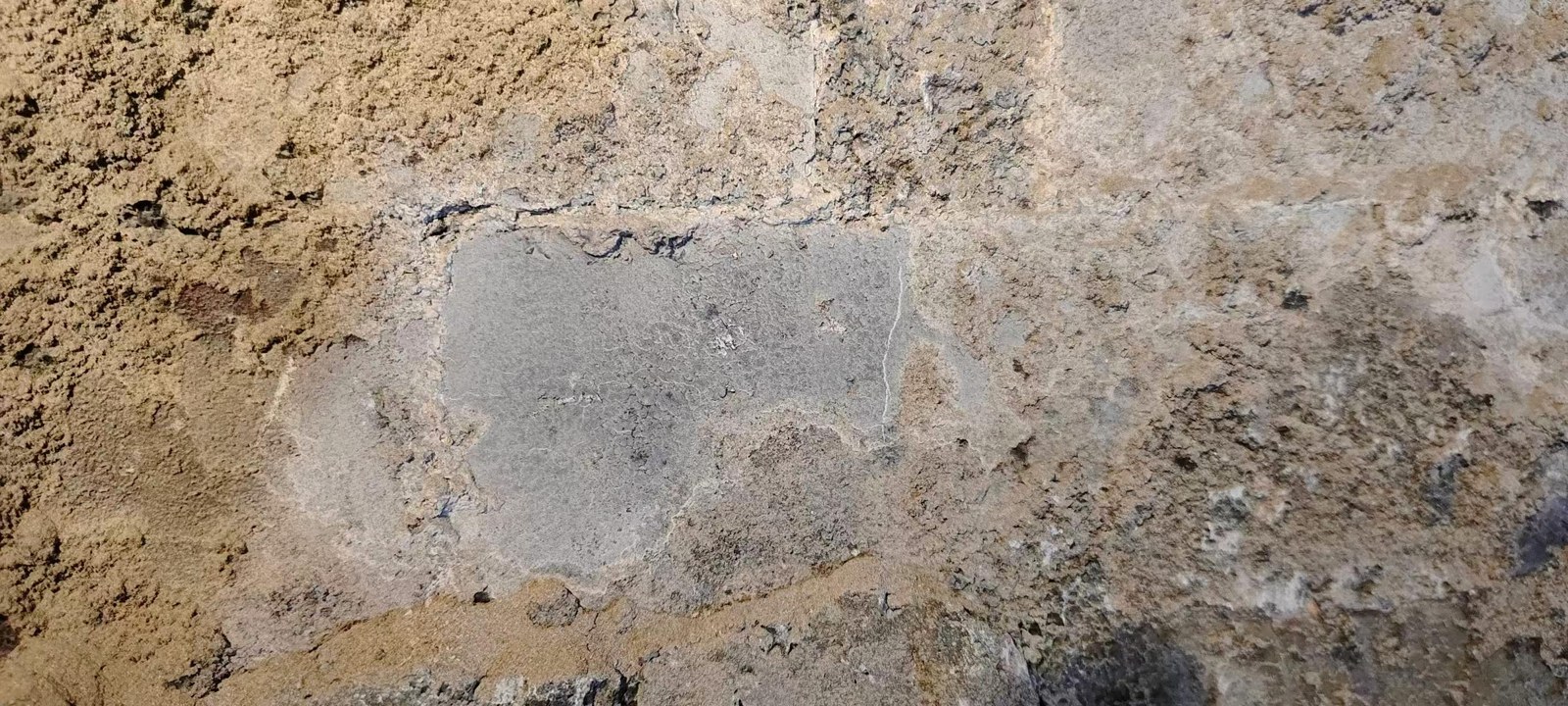
#2 boiler: rear arch covered by only a 2–3 cm deposit. Side walls and front / rear arches were flat and needed no de-slagging; the coating under the thin scale was intact.
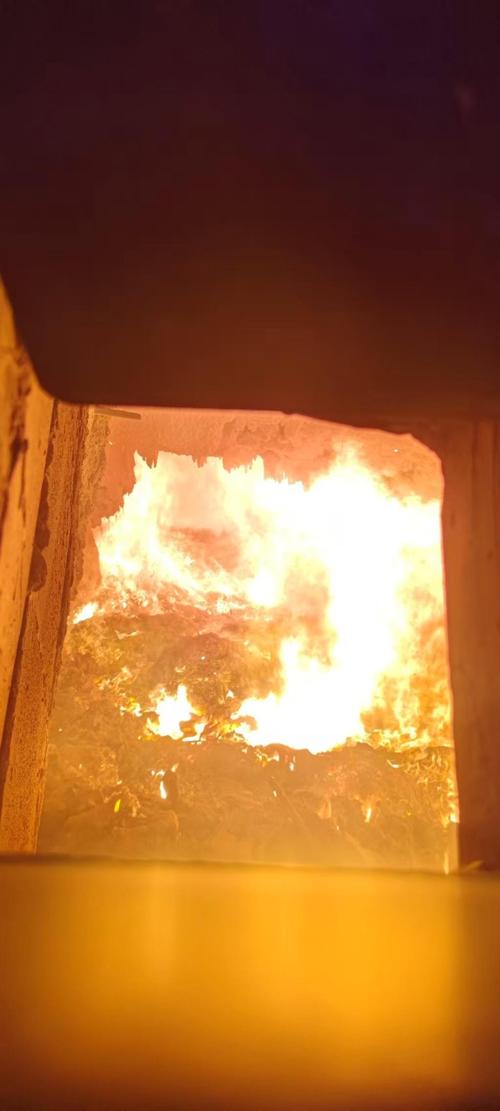
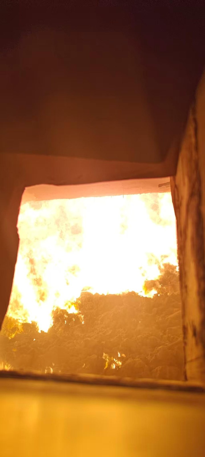
Operating results, 6 March 2026
Conclusions from the case
- Deposit thickness cut dramatically — comparing the rear arches of #1 and #2 boilers over the same period, a 90% reduction.
- The nature of the slagging changed: the mineralisation reaction between high-temperature molten-salt fly ash and the refractory is blocked, so the deposit layer is easy to clean.
- Refractories and boiler tubes are effectively protected against corrosion.
- Unplanned shutdowns caused by slag blocking the combustion chamber were completely eliminated. The rear arch was re-inspected on 11 August 2026 after further operation and remained in good condition.
2. The corrosion and slagging mechanism
The culprit is high-temperature molten-salt fly ash — fly ash carrying alkali metal ions, chloride ions and sulphate ions. With chlorine as the director, corrosion and slagging work hand in hand, accelerating attack on the substrate while the deposit layer sinters, hardens and thickens:
- 1Initial deposition: fly ash adheres physically and the deposit layer starts to grow.
- 2The deposit thickens, thermal resistance rises, and the outer tube-wall / interface temperature increases.
- 3Chlorides concentrate at the deposit–substrate interface.
- 4A liquid molten-salt film forms.
- 5Tubes: electrochemical corrosion accelerates and consumes wall metal. Refractories: Cl penetrates and destroys the structure.
- 6Tubes: corrosion product FeCl₂ is released into the deposit. Refractories: mineralisation reactions begin.
- 7Tubes: reaction with KCl / NaCl forms eutectic salts of even lower melting point. Refractories: Cl keeps migrating deeper.
- 8The deposit sinters, becoming denser and far harder to remove — then the cycle returns to step 2 and accelerates.
Corrosion and slagging therefore occur together and reinforce each other. The root of the solution is to stop chlorine from directing the process.
3. Validation data for the coating technology
1. Salt-bath validation
Carried out on boiler tube by Zhejiang Guiling Environmental Protection Technology Co., Ltd. A 4:6 mixture of sodium chloride and calcium chloride, melting point 500 °C. At this temperature a liquid molten-salt film forms and adheres to the tube surface, reproducing the conditions of a high-temperature superheater in service. Coated and uncoated tubes were exposed at 500 °C for 22 h and at 600 °C for 6 h, then air-cooled and washed. Conclusion: at 600 °C the coating gives strong protection against the mixed salt.
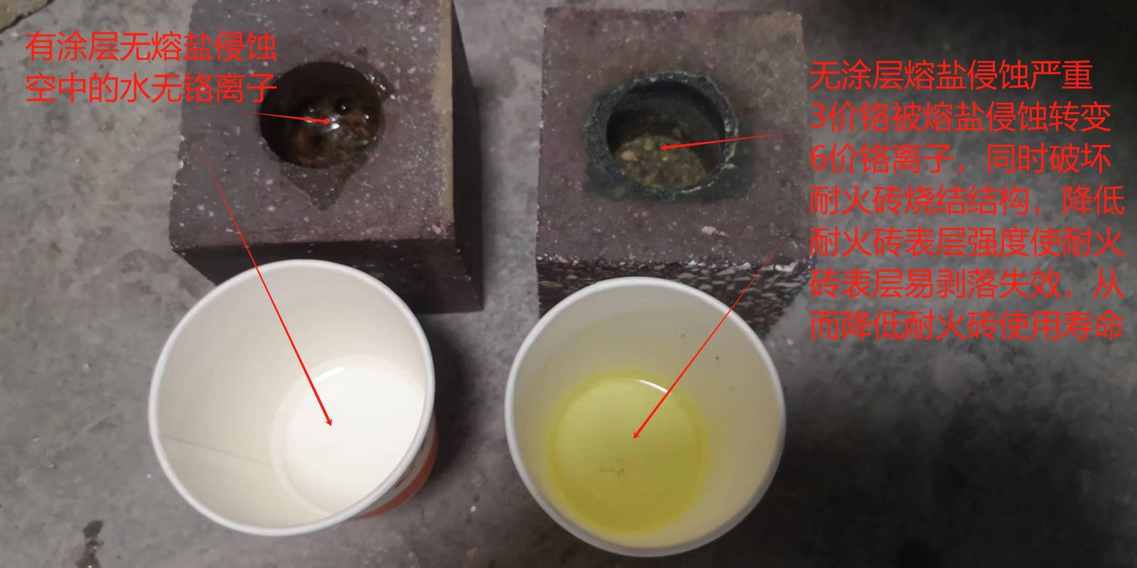
2. Dense refractory-brick 'crucible' validation
Verified at the Zhengzhou Jianxin Refractory Test Centre. A 4:6 sodium chloride / calcium chloride mix was held inside a dense refractory crucible at 1100 °C for 10 hours. Both the salt-bath and crucible tests confirmed that the coating can stop chlorine from driving the corrosion–slagging cycle.
3. Hazardous-waste rotary kiln and waste-heat boiler validation
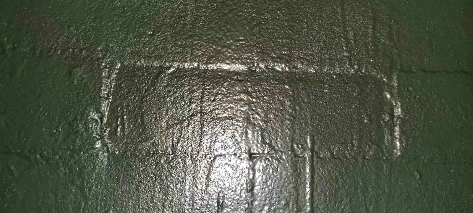
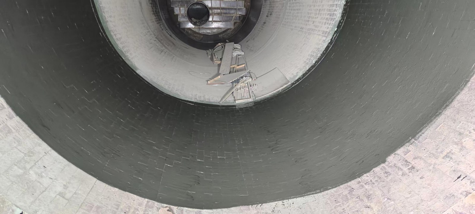
Dezhou Zhengshuo project. The waterwall sections at the ammonia-injection and ash-drop openings have exceeded 15 months in service, proving corrosion and erosion resistance. In the rotary kiln, the castable in the combustion zone was sprayed; after five months the coating had prevented any mineralisation reaction between the hazardous waste and the castable, while uncoated areas showed kiln-coating cracking and spalling.
4. Yixing Lingxia solid-waste project
Side-by-side comparison after commissioning: coated surfaces showed no corrosion, while the adjacent uncoated areas were severely corroded.
5. Everbright Environmental Protection hazardous-waste project
After six months of operation the kiln was stopped for inspection. Instead of the usual loss of more than 10 cm of lining, a thicker protective kiln coating had built up and the kiln internal diameter had reduced by 20 cm.
500 °C / 22 h — XRF analysis before cleaning
Uncoated — Bare tube: chlorine reached 48.24% at the molten-salt / air interface, 27.05% in the immersion zone and 25.62% in the mid vapour zone, with iron up to 20.14%.
Coated — Coated tube: chlorine fell to 34.42% at the interface, 15.27% in the immersion zone and 3.26–5.53% in the vapour zones, with iron only 0.22–0.80%.
600 °C / 6 h — wall-thickness change after cleaning
Uncoated — Bare tube: wall loss of 0.23 mm in the immersion zone, 0.15 mm in the mid vapour zone and 0.13 mm at the top.
Coated — Coated tube: no wall loss at all — thickness increased 0.13 mm in the immersion zone and 0.3 mm in the salt-adhesion band above the melt line. The coating in the immersion zone washed clean easily.
Conclusion: the high-melting ceramic-metal composite coating ends chlorine's role as director. It protects tubes and refractories from molten-salt fly-ash corrosion and changes the nature of the deposit — from bonded, mineralised and sintered slag to simple physical adhesion that is easy to remove.
Expected life in waste boilers: because the corrosive media in hazardous-waste incineration are far more aggressive than in municipal or industrial waste, and rotary-kiln tumbling with scraping scrap is far harsher than boiler service, the expected life in a waste-incineration boiler is one full overhaul cycle — so the return on this technology comfortably exceeds the investment.
4. Thermal-conductivity validation
Independent test report QLTC-25081101, issued by Foshan TsingLab New Materials Technology Co., Ltd. for Jinan High-Melt Corrosion Prevention Technology Institute. Thin-film samples were measured on a Netzsch LFA 467 laser flash apparatus at 25.1 °C and 48% RH, test temperature 500 °C. The report states that its results are intended for research, teaching, internal quality control and product-development purposes.
| Sample | Thermal diffusivity (mm²/s) | Density (g/cm³) | Specific heat (J/(g·°C)) | Thermal conductivity (W/(m·K)) |
|---|---|---|---|---|
| 1 | 7.812 | 7.515 | 0.622 | 36.514 |
| 2 | 8.918 | 7.274 | 0.591 | 38.338 |
The report records thermal conductivity of 36.514 and 38.338 W/(m·K) for the two samples and concludes that the coating is nearly five percentage points more conductive than the substrate, supporting heat transfer while protecting the surface.
5. Application
Process
- Surface preparation of tubes and refractories (sand blasting, cleaning)
- Spraying of the ceramic-metal composite coating
- Hot-air curing — spraying and curing repeated 4–5 times until the coating exceeds 0.45 mm
- Inspection and acceptance
- Sintering
Method
Waterwalls and the front / rear arches and side walls of the combustion chamber are coated on site, then sintered during start-up along the normal heat-up curve. High-temperature superheaters must be sintered off-line at our production base.
6. Value: energy saving, emission reduction, lower cost, higher output
- Rejects corrosion, extending the service life of castables, refractory bricks and boiler tubes and lowering replacement and overhaul costs.
- Eliminates unplanned shutdowns from tube bursts and slag blockage.
- Reduces maintenance labour cost.
- Cuts the cost of erecting and dismantling scaffolding.
- Fewer refractory replacements means fewer dry-out firings, sharply reducing fuel-oil cost.
- Less de-slagging work in the combustion chamber, reducing the safety risk of cleaning.
- Longer campaign length between outages and higher operating revenue.
- Higher heat-exchange efficiency and lower flue-gas exit temperature — energy saving, emission reduction and more power and heat output.
- Restores superheaters that had to be de-rated because of corrosion — or whose heat transfer dropped after cladding or overlay welding — raising power generation.
We look forward to building a better tomorrow with you
Talk to our engineers